
0
£0.00


Object detection/avoidance module for Arduino KY-032
KY032
Object detection/avoidance module for Arduino and other microcontroller projects
This module uses an IR diode and IR receiver that will detect if there is an object in front of the module. It also has 2 potentiometers to adjust the sensitivity of the module.
Voltage : 5VDC
Size : 44x18mm
|
£2.50
(inc VAT £3.00)
Percussion knock sensor module for Arduino KY-031
KY031
Percussion knock sensor module for Arduino and other microcontroller projects
This module is a switch that will detect being hit, it is not as sensitive as the vibration switch (KY-002) so can be used in projects that may be moving and an impact needs to be detected. This sensor acts like a switch that will "make" when the sensor is knocked.
Voltage :upto 5VDC
Size 19x15mm
|
£2.50
(inc VAT £3.00)
Photo interrupter module for Arduino KY-010
KY010
Photointerrupter module for Arduino and other microcontroller projects
This module has an optical slot device and 2 resistors fitted. The sensor will detect if an object is blocking the light between the emitter and receiver in the photointerrupter and can output a digital signal.
Voltage : 3.5 to 5VDC
Size 19x15mm
|
£2.50
(inc VAT £3.00)
Photoresistor module for Arduino KY-018
KY018
Photoresistor module for Arduino and other microcontroller projects
This module has a light dependent resistor (LDR) that will change value (resistance) depending on how much light there is on the sensor.
Voltage : 3.3 to 5VDC
Size 19x15mm
|
£2.50
(inc VAT £3.00)
PIR Sensor Module for Arduino
HCSR501
PIR sensor module for Arduino and other microcontroller projects
The HCSR501 is a PIR (Passive Infra-Red) sensor that can detect the presence of people by measuring the infrared radiation radiated by the body. It can be used in a vast and diverse number of projects, including but not limited to: automated lighting systems, burglar alarms, automated door systems, etc.
Principle of operation All objects with a temperature above absolute zero (0 kelvin) emit electromagnetic radiation. The higher the temperature of the object, the smaller the wavelength of the radiation emitted. The normal human body temperature is 37°C (310.2 kelvin) and it therefore emitts infrared radiation (mostly at a wavelength of 12µm). The PIR sensor can sense when a person has walked into its field of view by measuring the difference in the infrared radiation received from the ambient environment and the human body.
Voltage : 5-20VDC
Power Consumption: 64mA
Logic output: 3.3V Range: 7 metres, (<120°) Lock Time: 200 miliseconds Operating temperature range: between -15°C and 70°C |
£2.50
(inc VAT £3.00)
PT100 Waterproof Platinum RTD Temperature Sensor - 3 Wire
PT100
PT100 Waterproof Platinum RTD Temperature Sensor
The PT100 RTD (Resistance Temperature Detector) is a highly accurate, PTC temperature probe. It uses a thin strip of pure platinum that has a resistance of 100Ω at 0°C (±0.15°C) and 138.51Ω at 100°C (±0.35°C), thus providing a ~0.385Ω change per °C. The 3 wire version has one wire connected to one end of the platinum strip and two wires on the other end; this is to compensate for the voltage drop from the wires.
Specifications:
Temperature range: -50°C to 200°C Dimensions: 4mm x 100mm Cable length: 2m |
£10.00
(inc VAT £12.00)
Soil Hygrometer module for Arduino
KYSH
Soil hygrometer module with digital and analogue outputs for Arduino and other microcontroller projects
This module has a seperate 2 pronged moisture detector that is inserted into the soil and then connected to the comparitor board using the supplied link wires. It can give out a digital (High/Low) signal at a certain moisture level that can be set by adjusting the potentiometer on the board. There is also an analogue output to give you a more precise reading of the moisture level in the soil.
Voltage : 3.3 to 5VDC
Comparitor PCB Size 30x16mm
|
£2.50
(inc VAT £3.00)
Switch module for Arduino KY-004
KY004
Key switch module for Arduino and other microcontroller projects
This module has a small tactile switch that is normaly open and will close when pressed, it has a resistor connected in series with the switch so it can be used directly with a digital input on an Arduino when powered by 5VDC.
Voltage : upto 12VDC
Size 19x15mm
|
£2.50
(inc VAT £3.00)
Temperature and humidity module for Arduino KY-015
KY015
What is the KY-015 DHT11 Module?The KY015 is a temperature and humidity module for Arduino and other microcontroller projects
KY-015 module has a DHT-11 digital temperature and humidity sensor and a resistor. The DHT11 uses a thermistor for the temperature sensing and a capacitive humidity sensor along with an internal IC to give a digital output for both temperature and humidity.
Voltage : 3.3 to 5VDC Humidity range : 20% to 90% @ 5% RH accuracy Temperature range : 0C to 50C at 2C accuracy Size 30x15mm
How Can I use the KY-015 Module to monitor temperature and humidity?Here is an example project to measure temperature and humidity using the KY015 module and an Arduino Uno
Temperature and Humidity Sensor In this project, we will be building a weather station that can measure both temperature and humidity. This is what you will need: Tools
Components Arduino Uno x 1 or Arduino Nano x 1
Libraries Adafruit Unified Sensor Library Step 1First you will need to assemble the project. Connect everything together using the wiring diagram bellow for reference. 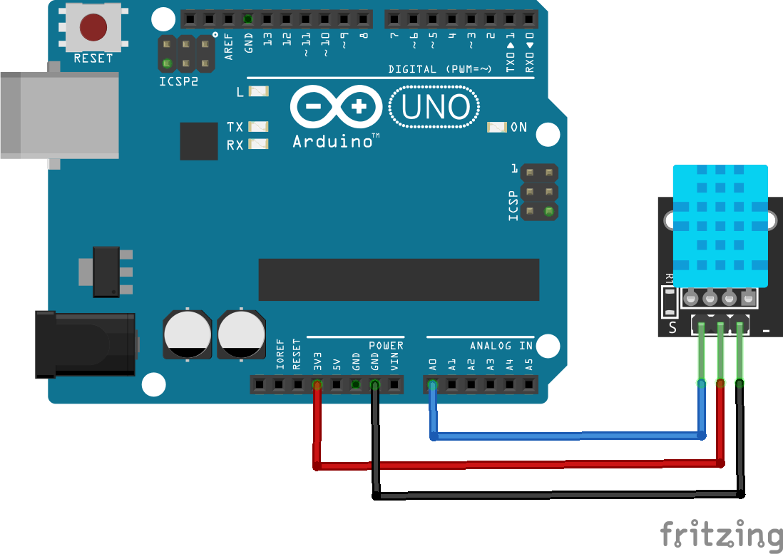 Connect the KY-015 sensor module to the Arduino
Ground - - - - - - - - - - Ground A 10KΩ pull-up resistor is built in to the KY-015 Step 2Connect your Arduino to the PC and install the above Libraries. If you don’t know how to do this, CLICK HERE and follow the “Installing Arduino Libraries” section.
Step 3We can now create the code to get this all working First, delete the code in the IDE window, then include the aforementioned libraries: <code class="language-css">#include "DHT.h"</code> This bit of code imports the DHT library and links it to the sketch. <code class="language-css">#define DHTPIN A0 #define DHTTYPE DHT11</code> This bit of code defines which pin is KY015 connected to and sets the type of sensor (KY015 uses DHT11) <code class="language-css">DHT dht(DHTPIN, DHTTYPE);</code> This bit of code initialises the sensor
<code class="language-css">void setup() {
  Serial.begin(115200);
  Serial.println(F("DHT11 test!"));
  dht.begin();
}</code>
The setup bit of code initialises serial output with baud rate of 115200 and prints DHT11 test! In the console
<code class="language-css">void loop() {
      delay(2000);</code>
This bit makes the Arduino wait 2 seconds between measurements <code class="language-css"> float h = dht.readHumidity();</code> Read humidity from the sensor <code class="language-css"> float t = dht.readTemperature();</code>Read temperature from the sensor
<code class="language-css">  Serial.print(F("Humidity: "));
  Serial.print(h);
  Serial.print(F("%  Temperature: "));
  Serial.print(t);
  Serial.println(F("°C "));
}</code>
Print the latest reading in serial monitor
Finished Code:
<code class="language-css">#include "DHT.h"

#define DHTPIN A0     // Digital pin connected to the DHT sensor
#define DHTTYPE DHT11   // DHT 11
DHT dht(DHTPIN, DHTTYPE);

void setup() {
  Serial.begin(115200);
  Serial.println(F("DHT11 test!"));

  dht.begin();
}

void loop() {
  delay(2000);

  float h = dht.readHumidity();
  float t = dht.readTemperature();

  Serial.print(F("Humidity: "));
  Serial.print(h);
  Serial.print(F("%  Temperature: "));
  Serial.print(t);
  Serial.println(F("°C "));
}</code>
|
£2.50
(inc VAT £3.00)
Temperature sensor module for Arduino KY-001
KY001
Temperature module for Arduino and other microcontroller projects
This module has a DS18B20 digital temperature, an LED and a resistor. It will give you a digital output that will vary depending on temperature.
Voltage : 3.3 to 5VDC
Temperature : -55C to 125C
Size 19x15mm
|
£2.50
(inc VAT £3.00)
Tiny RTC - Arduino real time clock module
RTC1
Tiny RTC module
This module uses the DS1307 chip, which can be used for keeping time in a very wide variety of projects. For example it can be used to add time stamps to sensor readings, display the time accurately or keep track of time even when there is no power supplied (although it will require a rechargeable CR2032 battery for this). The Tiny RTC supports the I2C protocol, which makes it very easy to interface with many microcontrollers.
Specs:
VCC: 5V DC
Battery (optional): CR2032
Power consumption: <500nA (in Battery Backup Mode)
RAM: 56 Byte, non-volatile
Memory: 32kb EEPROM
Dimensions: 27mm x 28mm x 8.4mm
|
£2.50
(inc VAT £3.00)
Ultrasonic Ranging Module for Arduino
HCSR04
Ultrasonic ranging module for Arduino and other microcontroller projects
This is a module with a 40kHz ultrasonic transmitter / receiver pair mounted on the front of a small PCB, with the required control circuitry on the back.
It sends a short 40kHz square wave out, and calculates the distance by recording the time it takes the wave to return to the sensor.
Voltage : 5VDC
Working Range : 20mm to 4500mm
Accuracy : 2mm
Example project:
HC SR04 Distance Measurement Tool
This article will demonstrate how to build a simple distance measuring device using the HC SR05 ultrasonic sensor board. This project can be used standalone as a way of measuring short distances or, it can be incorporated into other projects that require distance measuring. This sensor works best when the two transceivers are parallel to a solid surface, at a distance between 2cm to 450cm.
Here’s what you will need:
Tools
Step 1
First, you will need to connect the HCSR04 sensor to the Arduino. Simply use the male to female jumper leads to connect the two together as described below and in fig.1:
HCSR04 Arduino
VCC-----------------------------------------5V
Trig------------------------------------------D3
Echo----------------------------------------D2
GND---------------------------------------GND
Step 2
Solder the KY1602 module onto the 1602 LCD screen. Pin 1 on the KY1602 module is the one closest to the 4 data and power pins. Once soldered, you can now connect the LCD display to the Arduino as shown in fig. 1.
fig. 1 Step 3
Connect the Arduino to a computer and install the libraries mentioned above. If you need help installing the libraries, CLICK HERE for a quick tutorial.
Step 4 You can now start writing the code to get this all working: First, clear the IDE window. Then, include the aforementioned libraries:
Initialize the KY1602 I2C LCD driver (address 0x27 in this example) and specify the LCD display (in this case 16 characters, 2 rows):
Begin the void setup function. Initialize the LCD screen and turn on the backlight:
Add 100ms delay:
The completed code should look like this:
Step 5
Press the “Upload” button at the top (button with tick, located below “File”). The IDE will now compile the code and upload it to your Arduino (this will take a few moments).
Step 6
All done! The LCD will now start to display the distance calculated by the sensor.
|
£2.50
(inc VAT £3.00)
Waterproof Digital Temperature Probe for Arduino DS18B20
DS18B20
Waterproof digital temperature probe for Arduino and other microcontroller projects
This probe has a DS18B20 digital temperature IC inside a waterproof probe. It will give you a digital output that will vary depending on temperature.
Voltage : 3.3 to 5VDC
Temperature : -55C to 110C
Length : 1M
Example project:
DS18B20 High Accuracy Digital Thermometer.
This DS18B20 digital thermometer is extremely useful as a tool for measuring temperature for all kinds of different applications. It has a very wide temperature range (-55°C to 110°C) and high accuracy, especially at temperatures between -10°C to 85°C. In this project, we will be using an Arduino to read the temperature from the probe and display it on an LCD screen equipped with a KY1602 module.
Here’s what you will need:
Tools
Components
Arduino Uno x 1 or Arduino Nano x 1
Libraries
Step 1
First, you will need to connect the probe to the breadboard. This should be easy to do since the probe comes with pre-tinned leads. Simply push the ends of the leads into the breadboard sockets and use a 4.6kΩ pull-up resistor on the data pin as shown in fig.1. Now, you will need to connect the Arduino to the breadboard. Use the jumper leads to connect the male to male jumper leads to connect the power, ground and digital pin to the breadboard.
Step 2
Solder the KY1602 module onto the 1602 LCD screen. Pin 1 on the KY1602 module is the one closest to the 4 data and power pins. Once soldered, you can now connect the LCD display to the Arduino as shown in fig.1:
Fig. 1
Step 3
Connect the Arduino to your computer and install the libraries mentioned above. If you need help installing the libraries, CLICK HERE for a quick tutorial.
Step 4
You can now start writing the code to get this all working:
First, clear the IDE window. Then, include the aforementioned libraries:
Initialize the KY1602 I2C LCD driver (address 0x27 in this example) and specify the LCD display (in this case 16 characters, 2 rows):
Initialize the LCD display and turn on the LCD backlight. This is done inside the void setup function:
Start a while loop. This is done inside the void loop function:
Set the cursor to the first character and display the temperature in ºF and ºC:
Choose how often to update the screen (in this case, 800ms):
The completed code should look like this:
Step 4
Press the “Upload” button at the top (button with tick, located below “File”). The IDE will now compile the code and upload it to your Arduino (this will take a few moments).
Step 5
Done! If the connections are correct and there are no errors with the code, the LCD should display the temperature.
|


