 - Cricklewood Electronics")
0
£0.00
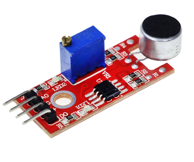
High sensitivity sound sensor module for Arduino KY-037
High sensitivity sound sensor module for Arduino and other microcontroller projects
This module uses a high sensitivity microphone to detect sound levels.
It also has a comparator to give a digital output and an analogue output.
A potentiometer can adjust the level for the digital output.
Voltage : 5VDC
Size 36x16mm
|


 Pitch Header Socket")


