The cookie settings on this website are adjusted to allow all cookies so that you have the very best experience. If you continue without changing your cookie settings, we'll assume that you are happy to receive all cookies on our website. However, if you would like to, you can change your settings at any time using the Change cookie settings link in the Special menu. 
    
 
+44 (0)20-84520161 Contact Us
Now FREE Delivery on UK mainland orders over £30+VAT

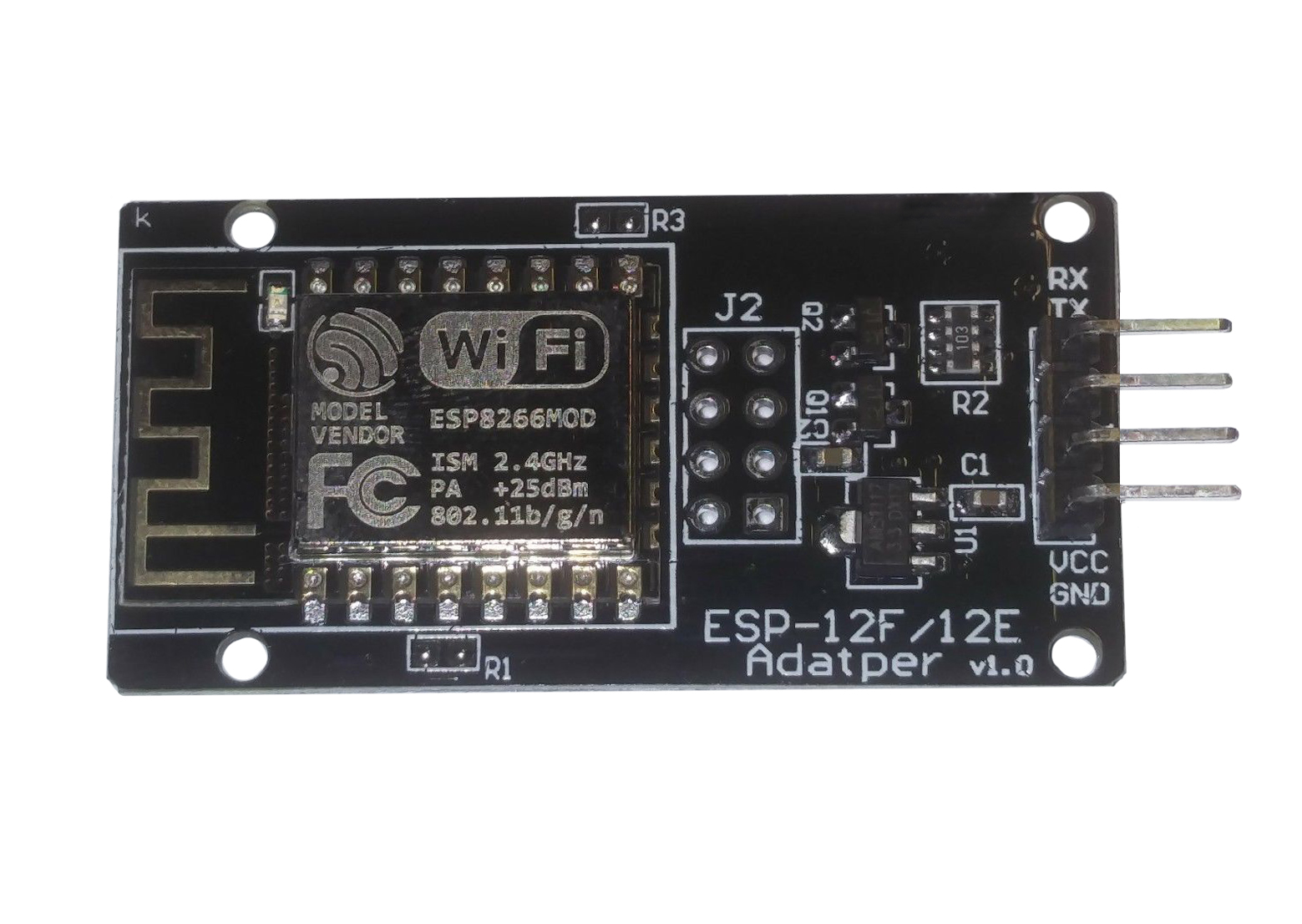
EPS8266 WiFi Module 2.4GHz for Arduino with Serial Connection ESP-12F

  • Details

  • Recommended

  • Send

Details

Item Number
ESP12F
Item Condition
New
Price
£7.50 (inc VAT £9.00)

Options

Quantity


  • Stripboard 2.5mm 0.1 inch Spacing 64x95mm

    Stripboard 2.5mm 0.1 inch Spacing 64x95mm

    Stripboard 2.54mm - 0.1 inch Copper Strips perforated at 0.1 inch (2.54mm) spacing 64 X 95mm

    CQ64
    £1.75
  • Stripboard 2.5mm 0.1 inch Spacing 119x455mm

    Stripboard 2.5mm 0.1 inch Spacing 119x455mm

    Stripboard 2.54mm - 0.1 inch Copper Strips perforated at 0.1 inch (2.54mm) sacing 119 x 455mm


    CQ455
    £8.75
  • 12.7mm-Self Adhesive PCB Pillars in Pack of 10

    12.7mm-Self Adhesive PCB Pillars in Pack of 10

    Pack of 10 Self Adhesive PCB Pillars in Nylon. 12.7mm length with 3M tape on base and snap-lock PCB fitting. For mounting PCBs without drilling.

    PPA12
    £1.75
  • Temperature and humidity module for Arduino KY-015

    Temperature and humidity module for Arduino KY-015

    What is the KY-015 DHT11 Module?

    The KY015 is a temperature and humidity module for Arduino and other microcontroller projects


    KY-015 module has a DHT11digital temperature and humidity sensor and a resistor. The DHT11 uses a thermistor for the temperature sensing and a capacitive humidity sensor along with an internal IC to give a digital output for both temperature and humidity.


    Voltage : 3.3 to 5VDC

    Humidity range : 20% to 90% @ 5% RH accuracy

    Temperature range : 0C to 50C at 2C accuracy

    Size 30x15mm


    How Can I use the KY-015 Module to monitor temperature and humidity?

    Here is an example project to measure temperature and humidity using the KY015 module and an Arduino Uno


    Temperature and Humidity Sensor

    In this project, we will be building a weather station that can measure both temperature and humidity.

    This is what you will need:

    Tools

    Jumper Leads (male to female)


    Components

    Arduino Uno x 1 or Arduino Nano x 1

    KY-15 sensor module


    Libraries

    DHT Sensor Library

    Adafruit Unified Sensor Library


    Step 1

    First you will nedd to assemble the project. Connect everything together using the wiring diagram bellow for reference.


    Connect the KY-015 sensor module to the Arduino

    KY-015                        Arduino   

    Ground - - - - - - - - - -  Ground
    Vcc - - - - - - - - - - - - - - 3v3
    Data - - - - - - - - - - - - -  A0

    A 10KΩ pull-up resistor is built in to the KY-015


    Step 2

    Connect your Arduino to the PC and install the above Libraries. If you don’t know how to do this, CLICK HERE and follow the “Installing Arduino Libraries” section.


    Step 3

    We can now create the code to get this all working

    First, delete the code in the IDE window, then include the aforementioned libraries:  

    #include "DHT.h"

    This bit of code imports the DHT library and links it to the sketch.

    #define DHTPIN A0
    #define DHTTYPE DHT11

    This bit of code defines which pin is KY015 connected to and sets the type of sensor (KY015 uses DHT11)

    DHT dht(DHTPIN, DHTTYPE);

    This bit of code initialises the sensor

    void setup() {
      Serial.begin(115200);
      Serial.println(F("DHT11 test!"));
      dht.begin();
    }

    The setup bit of code initialises serial output with baud rate of 115200 and prints DHT11 test! In the console

    void loop() {
       delay(2000);

    This bit makes the Arduino wait 2 seconds between measurements

      float h = dht.readHumidity();

    Read humidity from the sensor

      float t = dht.readTemperature();
    Read temperature from the sensor
      Serial.print(F("Humidity: "));
      Serial.print(h);
      Serial.print(F("%  Temperature: "));
      Serial.print(t);
      Serial.println(F("°C "));
    }

    Print the latest reading in serial monitor


    Finished Code:

    #include "DHT.h"
    
    #define DHTPIN A0 // Digital pin connected to the DHT sensor
    #define DHTTYPE DHT11 // DHT 11
    DHT dht(DHTPIN, DHTTYPE);
    
    void setup() {
      Serial.begin(115200);
      Serial.println(F("DHT11 test!"));
    
      dht.begin();
    }
    
    void loop() {
      delay(2000);
    
      float h = dht.readHumidity();
      float t = dht.readTemperature();
    
      Serial.print(F("Humidity: "));
      Serial.print(h);
      Serial.print(F("%  Temperature: "));
      Serial.print(t);
      Serial.println(F("°C "));
    }


    KY015
    £2.50
  • Waterproof Digital Temperature Probe for Arduino DS18B20

    Waterproof Digital Temperature Probe for Arduino DS18B20

    Waterproof digital temperature probe for Arduino and other microcontroller projects

     
    This probe has a DS18B20 digital temperature IC inside a waterproof probe. It will give you a digital output that will vary depending on temperature.
     
    Voltage : 3.3 to 5VDC
    Temperature : -55C to 110C
    Length : 1M

    Example project: 
     

    DS18B20 High Accuracy Digital Thermometer.

     
    This DS18B20 digital thermometer is extremely useful as a tool for measuring temperature for all kinds of different applications. It has a very wide temperature range (-55°C to 110°C) and high accuracy, especially at temperatures between -10°C to 85°C.  In this project, we will be using an Arduino to read the temperature from the probe and display it on an LCD screen equipped with a KY1602 module.
     
    Here’s what you will need: 
     
    Tools
     
    Components

    Libraries

    Step 1
    First, you will need to connect the probe to the breadboard. This should be easy to do since the probe comes with pre-tinned leads. Simply push the ends of the leads into the breadboard sockets and use a 4.6kΩ pull-up resistor on the data pin as shown in fig.1. Now, you will need to connect the Arduino to the breadboard. Use the jumper leads to connect the male to male jumper leads to connect the power, ground and digital pin to the breadboard. 
     
    Step 2
    Solder the KY1602 module onto the 1602 LCD screen. Pin 1 on the KY1602 module is the one closest to the 4 data and power pins. Once soldered, you can now connect the LCD display to the Arduino as shown in fig.1:
     

    Fig. 1


    Step 3
    Connect the Arduino to your computer and install the libraries mentioned above. If you need help installing the libraries, CLICK HERE for a quick tutorial.
     
    Step 4
    You can now start writing the code to get this all working: 


    First, clear the IDE window. Then, include the aforementioned libraries:
    
    #include <DS18B20.h>
    #include <LCD_I2C.h>


    Initialize the KY1602 I2C LCD driver (address 0x27 in this example) and specify the LCD display (in this case 16 characters, 2 rows):
     
    DS18B20 ds(12);
    LCD_I2C lcd(0x27, 16, 2);


    Initialize the LCD display and turn on the LCD backlight. This is done inside the void setup function:
     
    void setup() {
    lcd.begin();
    lcd.backlight();
    }


    Start a while loop. This is done inside the void loop function:
     
    void loop() {
    while (ds.selectNext()) {


    Set the cursor to the first character and display the temperature in ºF and ºC:
     
    lcd.setCursor(0,0);
      lcd.print(ds.getTempC());
      lcd.print((char)223);
      lcd.print("C");
      lcd.setCursor(0,1);
      lcd.print(ds.getTempF());
      lcd.print((char)223);
      lcd.print("F");
      }


    Choose how often to update the screen (in this case, 800ms):
     
      delay(800);
    }


    The completed code should look like this:
     
    #include <DS18B20.h>
    #include <LCD_I2C.h>
    
    DS18B20 ds(12);
    LCD_I2C lcd(0x27, 16, 2);
    
    void setup() {
      lcd.begin();
      lcd.backlight();
    }
    
    void loop() {
      while (ds.selectNext()) {
      lcd.setCursor(0,0);
      lcd.print(ds.getTempC());
      lcd.print((char)223);
      lcd.print("C");
      lcd.setCursor(0,1);
      lcd.print(ds.getTempF());
      lcd.print((char)223);
      lcd.print("F");
      }
      delay(800);
    }


    Step 4
    Press the “Upload” button at the top (button with tick, located below “File”). The IDE will now compile the code and upload it to your Arduino (this will take a few moments).
     
    Step 5
    Done! If the connections are correct and there are no errors with the code, the LCD should display the temperature. 
     
    DS18B20
    £3.50
  • I2C Parallel to Serial Converter for Arduino Type LCD Screens

    I2C Parallel to Serial Converter for Arduino Type LCD Screens

    I2C Paralel to 2 Pin Serial converter for Arduino type LCD screens

     
    This converter can be soldered directly to a standard 1602 LCD screen to convert it to the more convenient 2 pin serial (I2C) used in many Arduino projects.
    There is a removable jumper to allow connection with both backlit and non backlit screens.
    A potentiometer can adjust the brightness & contrast of the LCD.
     
     
    Connections
    GND = Ground
    VCC =  5V
    SDA = Serial Data Line
    SCL = Serial Clock Line 
     
     
    KY1602
    £2.50
  • EPS8266 WiFi Module 2.4GHz for Arduino with Serial Connection ESP-01

    EPS8266 WiFi Module 2.4GHz for Arduino with Serial Connection ESP-01

    2.4GHz Serial WiFi Module for Arduino and other IOT or Microcontroller projects

    The popular ESP8266 microchip with full function WiFi plus it's own microcontroller.
    Can be used to add WiFi to your microcontroller project or programmed directly from the Arduino IDE to work independently.
    It should NOT be powered from 5V or be directly connected to the digital connections on an Arduino item, as this can damage the module.
    Supplied with a pre-soldered 8 way header.
     
    Voltage : 1.7-3.5VDC
    Frequency : 2.4GHz
    Wireless Standard : 802.11 b/g/n
    Dimensions : 14mm x 25mm
    ESP01
    £3.25
  • USB Programmer for EPS8266 in the ESP-01 Module

    USB Programmer for EPS8266 in the ESP-01 Module

    USB Programmer for ESP-01 WiFi Module

    This programmer makes setting up the ESP-01 much easier and safer, the ESP-01 just plugs into the 8 way header on the programmer and will be provided with the correct working and programming voltages. The module uses the popular CH340 USB-UART bridge to allow the ESP-01 to easily comunicate with the USB.
     
    Voltage : 5VDC (from USB)
    Dimensions : 17mm x 34mm (49mm including USB plug)
    ESPROG
    £3.50
  • Tiny RTC - Arduino real time clock module

    Tiny RTC - Arduino real time clock module

    Tiny RTC module  

    This module uses the DS1307 chip, which can be used for keeping time in a very wide variety of projects. For example it can be used to add time stamps to sensor readings, display the time accurately or keep track of time even when there is no power supplied (although it will require a rechargeable CR2032 battery for this). The Tiny RTC supports the I2C protocol, which makes it very easy to interface with many microcontrollers. 
     
    Specs: 
    VCC:  5V DC
    Battery (optional): CR2032
    Power consumption: <500nA (in Battery Backup Mode)
    RAM: 56 Byte, non-volatile
    Memory: 32kb EEPROM
    Dimensions: 27mm x 28mm x 8.4mm
     
    RTC1
    £2.50

Send to Friend

: *
: *
: *
Type the characters you see in the picture:


*

2.4GHz Serial WiFi module for Arduino and other IOT or microcontroller projects

 
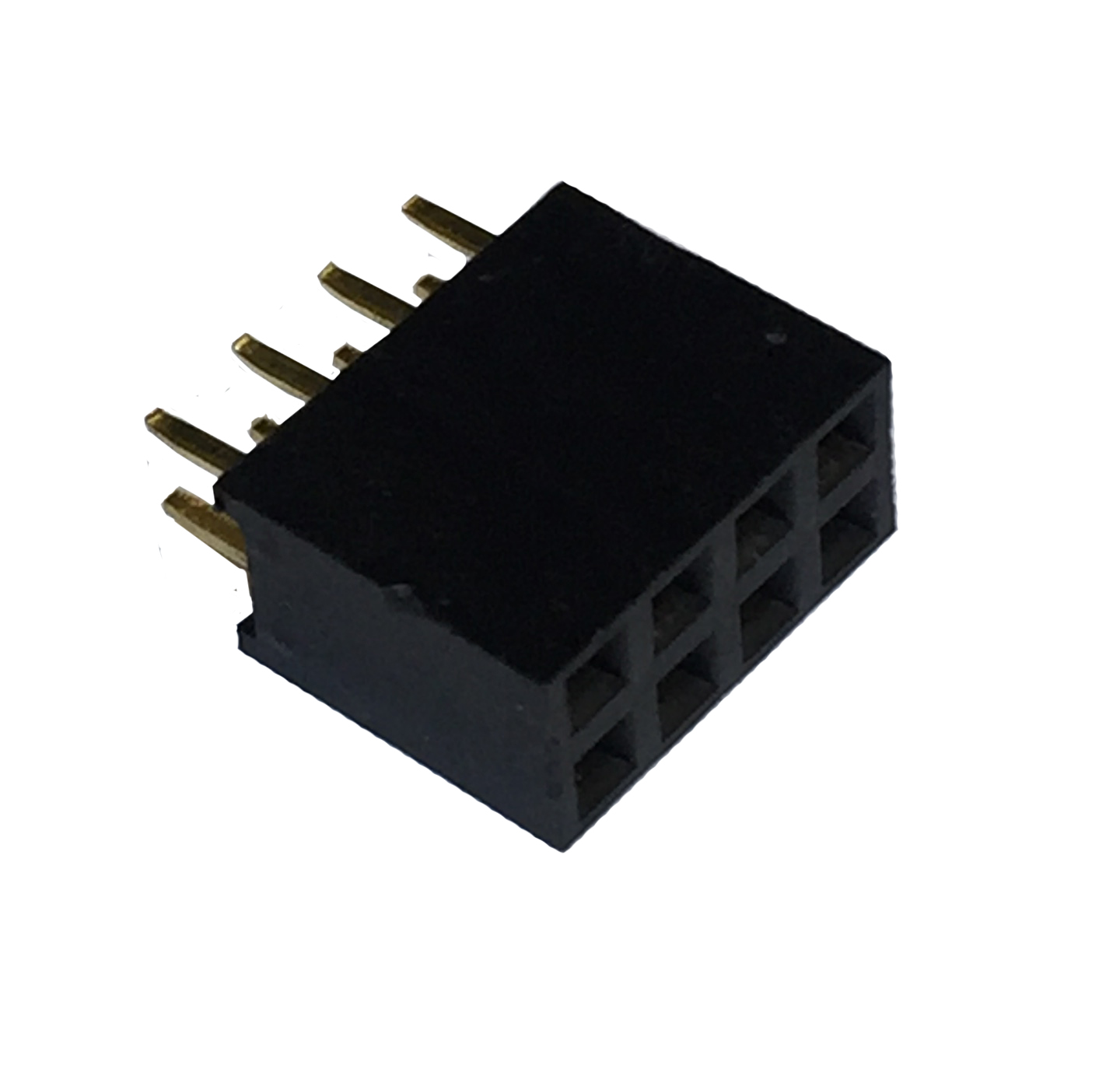
This module uses the popular ESP8266 microchip with full function WiFi as well as its own microcontroller. This module can be used to add WiFi to your microntroler project or can be programed directly from the arduino IDE to work independently. This module also has a built in regulator so it can be powered directly from 5VDC. Supplied with 8 way header.
 
Voltage : 5VDC
Frequency : 2.4GHz
Wireless Standard : 802.11 b/g/n
Dmensions : 24mm x 46mm

Trustpilot