| Now FREE Delivery on UK mainland orders over £30+VAT |
CO2 and VOC indoor air quality sensor module for Arduino and other microcontroller projects
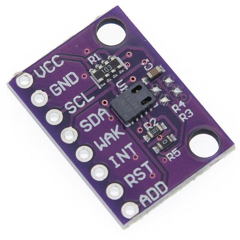
This module has a CCS811 module that is an ultra low powered digital gas sensor using a metal oxide multi compound sensor. The module uses the onboard MCU to manage the sensor and provide the needed Analogue to Digital conversion and I2C interface making it simple to add to your project. It will detect a wide range of VOCs including Carbon Monoxide and can convert this to an eCO2 (equivalent CO2) value.
Voltage: 3.3VDC
Size: 21x15mm
Here is an example project for an air quality meter using the CJUMCU-811, an Arduino Uno and a 1602 LCD screen with a KY1602 to display CO2 levels and air quality:
In this project, we will be building an air quality station that can measure eCO2 (estimated carbon dioxide) levels and a wide range of VOCs (Volatile Organic Compounds). High VOC levels can contribute to a wide range of health complications and high CO2 levels (>1000ppm) can impair normal cognitive function, so it is useful to be able to monitor them.
Here’s what you will need:
Tools
Soldering Iron
Solder
Jumper Leads (male to female)
Components
CJMCU811 x 1
LCD1602B LCD screen x1
Arduino Uno x 1 or Arduino Nano x 1
KY1602 Parallel to Serial converter
Libraries
Step 1
First you will need to assemble the project. The CJMCU should come with a set of pin headers that need to be soldered directly on it and the KY1602 should be soldered directly to the back of the LCD screen. Now, connect everything together using the wiring diagram below for reference.
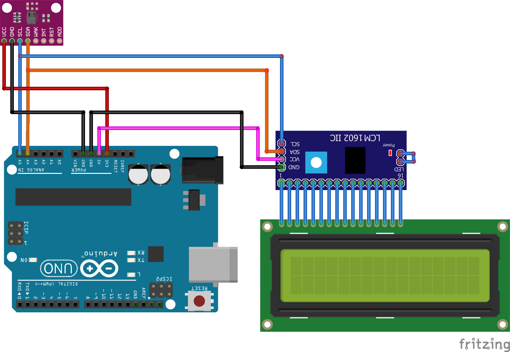
Connecting the CJMCU811 to an Arduino Connecting the KY1602 to an Arduino and a 1602 LCD
CJMCU Arduino KY1602 Arduino LCD
VCC----------------------------3.3V VCC-----------------------------5V
GND----------------------------GND GND----------------------------GND
SCL------------------------------A5 SCL-----------------------------A5
SDA-----------------------------A4 SDA-----------------------------A4
Pins 1-16---------------------------------------Pins 1-16*
*pin 1 on the KY1602 is the one nearest to the 4 data and power pins
Step 2
Connect your Arduino to the PC and install the above Libraries. If you don’t know how to do this, CLICK HERE and follow the “Installing Arduino Libraries” section.
Step 3
We can now create the code to get this all working:
First, delete the code in the IDE window, then include the aforementioned libraries:
#include <LCD_I2C.h>
#include <Wire.h>
#include "SparkFunCCS811.h"
Now, We need to declare the I2C devices and their addresses:
#define CCS811_ADDR 0x5B
LCD_I2C lcd(0x27, 16, 2);
CCS811 sensor(CCS811_ADDR);
Initialize the I2C devices and turn on lCD backlight in the setup function:
void setup()
{
  Wire.begin();
  lcd.begin();
  lcd.backlight();
Start serial communication
Serial.begin(115200);
delay(1000);
Check to see if the CJMCU is configured correctly, otherwise display error message:
if (sensor.begin() == false)
  {
  Serial.print("Sensor error. Check connection");
  while (1);
  }
Starting the void loop function. Check to see if the data from the sensor is available, and if so, read and calculate the results:
if (sensor.dataAvailable())
  {
  sensor.readAlgorithmResults();
Send the data via serial port:
Serial.print("CO2[");
  Serial.print(sensor.getCO2());
  Serial.print("] tVOC[");
  Serial.print(sensor.getTVOC());
Display the same data on the LCD display:
lcd.setCursor(0,0);
lcd.print("Est. CO2 - ");
  lcd.print(sensor.getCO2());
  lcd.setCursot(0,1);
lcd.print("Tot. VOC - ");
  lcd.print(sensor.getTVOC());
  }
Add 10ms delay to prevent overloading the I2C bus:
delay(10);
The completed code should look like this:
/*
Connecting the CJMCU811 to an Arduino Uno or an Arduino Nano:

CJMCU811       Arduino
VCC-------------->3V3
GND-------------->GND
SCL-------------->A5
SDA-------------->A4
*/

#include <lcd_i2c.h>
#include <wire.h>
#include "SparkFunCCS811.h"
LCD_I2C lcd(0x27, 16, 2); //Address of the KY1602 module
#define CCS811_ADDR 0x5A //if it doesn't work, change to 0x5B

CCS811 sensor(CCS811_ADDR);

void setup()
{
  Wire.begin(); //Initialize I2C Hardware

  lcd.begin(); // If you are using more I2C devices using the Wire.h library, use lcd.begin(false)

  lcd.backlight();

  Serial.begin(115200);  //Starting serial communication
  delay(1000);


  if (sensor.begin() == false)
  {
  Serial.print("Sensor error. Check connection");
  while (1);
  }
}

void loop()
{
  if (sensor.dataAvailable())//Check to see if data is ready with .dataAvailable(). if statement checking to see
  {
  //If so, have the sensor read and calculate the results.
  sensor.readAlgorithmResults();

  Serial.print("CO2["); //Returns estimated CO2 reading
  Serial.print(sensor.getCO2());
  Serial.print("] tVOC[");//Returns calculated total VOC reading
  Serial.print(sensor.getTVOC());

  lcd.setCursor(0,0);
  lcd.print("Est. CO2 - ");
  lcd.print(sensor.getCO2());
  lcd.setCursor(0,1);
  lcd.print("Tot. VOC - ");
  lcd.print(sensor.getTVOC());
  }
  delay(10); //Prevents overloading of the I2C bus
}
Step 4 Press the “Upload” button at the top (button with tick, located below “File”). The IDE will now compile the code and upload it to your Arduino (this may take a few moments).
Step 5 To check if everything is working, open the serial monitor from the Arduino IDE (magnifying glass button in the top right corner) and see if you can get a reading. The CJMCU has to be left on for 24 hours before it will give a correct reading. If everything is connected correctly, the LCD should also show readings from the sensor.
Step 6 That’s it! You should now have a fully working air quality sensor. Now all you need to decide is what sort of enclosure you want to put it in. You can look at our high quality boxes HERE for ideas.