| Now FREE Delivery on UK mainland orders over £30+VAT |


Waterproof digital temperature probe for Arduino and other microcontroller projects
This probe has a DS18B20 digital temperature IC inside a waterproof probe. It will give you a digital output that will vary depending on temperature.
Voltage : 3.3 to 5VDC
Temperature : -55C to 110C
Length : 1M
Example project:
DS18B20 High Accuracy Digital Thermometer.
This DS18B20 digital thermometer is extremely useful as a tool for measuring temperature for all kinds of different applications. It has a very wide temperature range (-55°C to 110°C) and high accuracy, especially at temperatures between -10°C to 85°C. In this project, we will be using an Arduino to read the temperature from the probe and display it on an LCD screen equipped with a KY1602 module.
Here’s what you will need:
Tools
Components
Arduino Uno x 1 or Arduino Nano x 1
Libraries
Step 1
First, you will need to connect the probe to the breadboard. This should be easy to do since the probe comes with pre-tinned leads. Simply push the ends of the leads into the breadboard sockets and use a 4.6kΩ pull-up resistor on the data pin as shown in fig.1. Now, you will need to connect the Arduino to the breadboard. Use the jumper leads to connect the male to male jumper leads to connect the power, ground and digital pin to the breadboard.
Step 2
Solder the KY1602 module onto the 1602 LCD screen. Pin 1 on the KY1602 module is the one closest to the 4 data and power pins. Once soldered, you can now connect the LCD display to the Arduino as shown in fig.1:
Fig. 1
Step 3
Connect the Arduino to your computer and install the libraries mentioned above. If you need help installing the libraries, CLICK HERE for a quick tutorial.
Step 4
You can now start writing the code to get this all working:
First, clear the IDE window. Then, include the aforementioned libraries:
Initialize the KY1602 I2C LCD driver (address 0x27 in this example) and specify the LCD display (in this case 16 characters, 2 rows):
Initialize the LCD display and turn on the LCD backlight. This is done inside the void setup function:
Start a while loop. This is done inside the void loop function:
Set the cursor to the first character and display the temperature in ºF and ºC:
Choose how often to update the screen (in this case, 800ms):
The completed code should look like this:
Step 4
Press the “Upload” button at the top (button with tick, located below “File”). The IDE will now compile the code and upload it to your Arduino (this will take a few moments).
Step 5
Done! If the connections are correct and there are no errors with the code, the LCD should display the temperature.
|
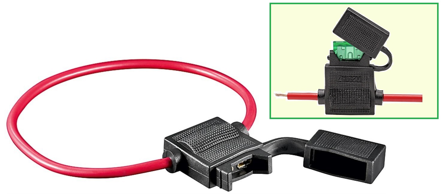
Complete with Short Red Cable, and housing cover


")